 |
 |
| Home | Software | Guitar Amps etc. | Publications | Secure | Contact |
| Main Amp Page | DSL Clean/Crunch Footswitch | DSL FX Loop Modification | DSL FX Loop Measurements |
JCM2000 Marshall DSL 50 / 100 FX Loop Modification"GTS MDSL FXM 1"Improves Loop Transparancy at Low VolumesMany people complain about the effects loop (fx loop) on these amplifiers. Whilst some of the problems I believe are caused by losses in the pedals/fx units themselves I did find the amp sounded horrible with the loop on at low volumes - the sort of levels you might use at home to practice. Try this: Use a short piece of cable to loop the FX send and return jacks - this enables the FX loop but returns exactly what was sent from the loop. Select the red channel and turn the volume all the way to zero. Play your guitar - notice the trebly sound coming through even at zero volume? As you turn up the volume you bring in your normal amp sound but the tinny sound remains. I found that I didnt want to use the FX loop because of this. If you turn the amp up, you can hardly notice the effect and it sounds much better - but I just couldnt get on with the low volume sound at all.
|
Dual Op-Amp and CrosstalkThe DSL 50/100 amplifiers use a number of dual op-amp integrated circuits to reduce total chip count and cost of the PCBs. This practise leads to a compromise between price, complexity and sound quality. The schematic for the FX loop buffer circuit is shown below with the same component designations as on my amplfier. Note that a single non-inverting op-amp buffer circuit is used. |
 |
IC2a is used to buffer the audio signal coming from the selected pre-amp channel after some attentuation to keep the audio signal within the limits of the op-amp at high volumes. On its own there is little wrong with the circuit, however the audio path between R40, R39 and IC2a +ve input is a high impedance circuit and is susceptible to noise pickup, this is the source of the problem. The other half of the RC4558 op-amp (IC2b) is used in the tone circuits around the presence control and deep switching elements. The position of the IC on the board is also close to the tone circuits that use full value pre-amp audio voltages, as they are situated before the volume controls. The proximity of the susceptible circuits to the large tone control voltages allows the buffer to pickup the higher frequency audio signals and transmit them into the FX loop.
|
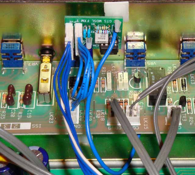
FX Loop ModificationTo eliminate this problem, the FX buffer circuit has been re-created on a seperate PCB that can be installed much closer to where it is actually needed, near the channel/fx loop relays and the CON10 FX loop connector. Care was taken to minimise the track lengths within the noise susceptible areas and to use low noise metal film components. CON10 has IC voltage supplies and the FX send signals. Hence, the modified circuit sits in between CON10 on the main tone control/channel selector PCB and the corresponding connector on the rear PCB.
|
FX Loop MeasurementsTo confirm what is going on in terms of the low volume FX loop performance I have made some measurements using a sine wave sweep to monitor the frequency response of the amplifier with no FX loop, standard FX loop and modified effects loop. The response of the amplifier with no loop is the reference level. Ideally when the FX loop is engaged and linked back, the measured response should be identical to the NO LOOP response - any deviation results in a noticable change in tone. |
Red Channel Volume 0.5
It is clear that at low volumes the standard FX loop response is dominated by high frequency content that is simply do not appear when the loop is not used. It is shows that the improved FX modification circuit, positioned away from the tone circuit PCB tracks has a response almost identical to the non-loop response.
|
Red Channel Volume >1 (just above 1)
As the volume is increased beyond level 1 (which is still rather loud on a 100W DSL amplifier for home use!) the standard loop starts to look a lot more like the non-loop response, this is improved further by use of the modification kit. Further above level 1, which is too loud when you have neighbours like mine, the FX loop thinning is hardly noticable.
|
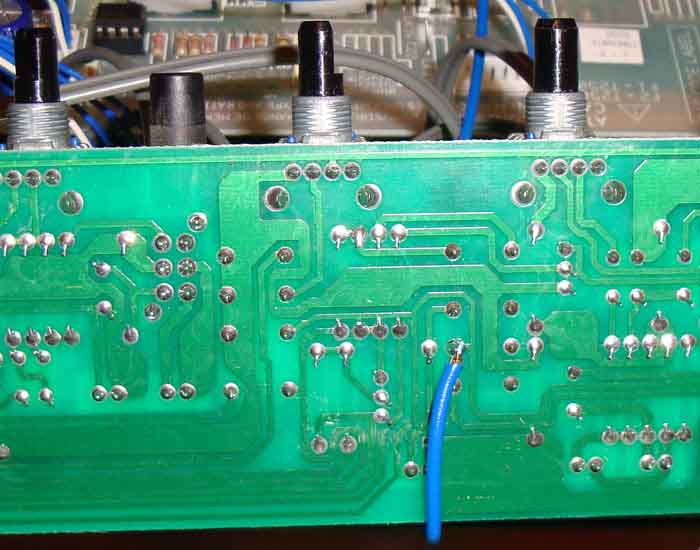
InstallationInstallation requires removing the patch cable from CON10 on the front PCB and plugging into FX connector on new PCB. Supplied patch cable goes from TONE connector back to CON10. Single blue wire should be soldered onto RL3 shown below (Note: Front PCB will need to be taken out to access solder point). Supplied PCB stands can be used to mount the board into the case.
|
Mounted modification PCB
|
Solder Point for Audio Pick-up - RL3b
|
Note:High voltages are present inside amplifiers even when disconnected from the mains. Application of this modification requires dis-assembly of the amplifier and should not be undertaken if you are not experienced or qualified to work with electronic systems of this type. I cannot accept responsibilty for any damage to either the amplifier or the operator due to incorrect installation of this modification. As such, this modification is only offered for sale to those who are qualified or experienced in tube amplifier repair/maintenance. Pricing/PurchasingThe modification, consisting of complete PCB, mounting stand-offs, patch cable and instructions is priced at £17 including delivery to the UK. Postage to Europe is an additional £1.50, postage to anywhere else is an additional £3. Please contact me by email here to arrange purchase of the kits and payment through paypal. |