 |
 |
| Home | Software | Guitar Amps etc. | Publications | Secure | Contact |
| Main Amp Page | DSL Clean/Crunch Footswitch | DSL FX Loop Modification | DSL FX Loop Measurements |
JCM2000 Marshall DSL 50 / 100 Clean Crunch Footswitch"GTS MDSL FSW 2 "
|
|
 |
|
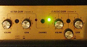
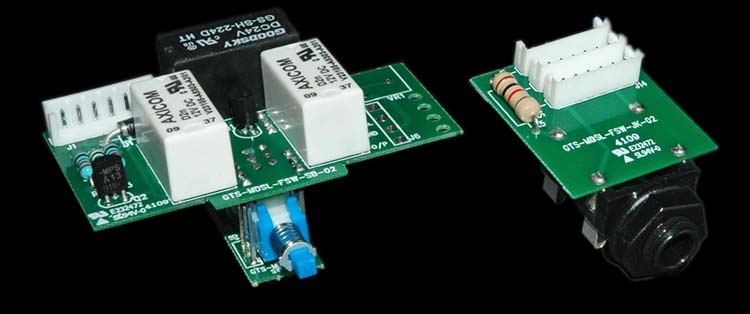
DescriptionThis mod kit provides everything necessary to make the clean/crunch channels selectable via a footswitch. The drop-in relay assembly (left) replaces the standard push button latching switch. This assembly routes the switch signals up onto the relay board which perform the same job as the original 4 pole changeover switch. However, the clean/crunch modes are now selectable not only by the on-board switch (as before) but also by a footswitch connected to the jack assembly (right). The jack assembly is designed to fit in place of the reverb footswitch jack (which is not commonly used) however some users have drilled additional holes in the rear plate of the amp to maintain the footswitchable reverb. In addition to providing an active mode switch, a 3rd relay allows a further modification to provide a dedicated crunch volume control. Thus allowing complete "Triple Channel" control on a DSL amplifier. Further, No PCB tracks need to be cut therefore, assuming no extra holes were drilled for a custom install, the modification can be removed and the original components re-fitted to the amp returning it to stock.
|
|
|
|
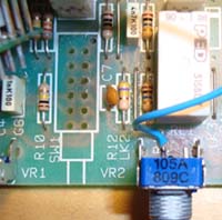
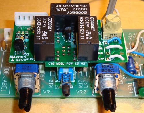
Installation - SummaryThis is a summary of the installation process. A full guide can be provided on request showing all the relevant pick-up points and descriptions of each step. |
|
|
 |
|
|
|
|
Further InformationFull installation instructions can be provided on request. At the time of posting, over 50 of these mods have been supplied and successfully installed. Some feedback and discussion of the mod kit can be found in the following post on the Marshall Forum website which was started during the development of this mod. Note: This mod is provided assembled however it should be treated as a kit of components that can be used in order to modify your DSL 50/100 amplifier. As such it is not an end product or appliance and its success requires that the installer is competent with solder / de-solder techniques. |
|
Note:High voltages are present inside amplifiers even when disconnected from the mains. Application of this modification requires dis-assembly of the amplifier and should not be undertaken if you are not experienced or qualified to work with electronic systems of this type. I cannot accept responsibility for any damage to either the amplifier or the operator due to incorrect installation of this modification. As such, this modification is only offered for sale to those who are qualified or experienced in tube amplifier repair/maintenance. |
|
Purchase / Pricing Information
The mod kits are assembled to order. As such, please contact me to discuss payment information and lead times. Normally kits are available within 2 weeks depending on work commitments etc. The original run of kits for the Marshall Forum members is now over as all PCBs have been used. The current run however is in progress, the latest pricing is £79 UK Sterling, including postage within the EU. Postage to the rest of the world is an extra £9.00 (using the Royal Mail Internation Tracked and Signed service where available). |
|